Overview

Instructions

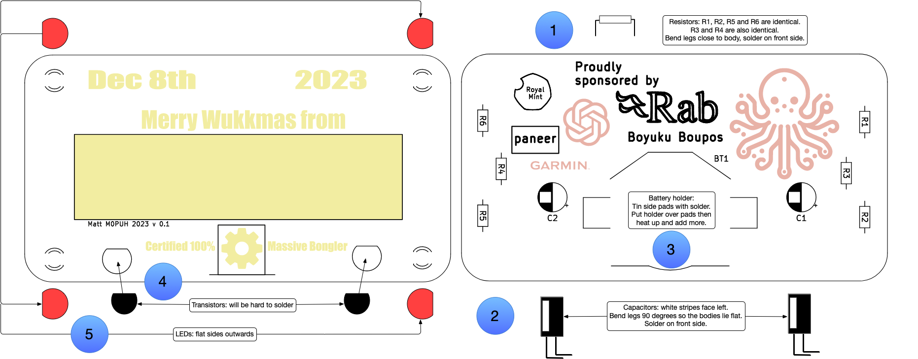
Refer to numbers in diagram above.

  1. Look at the board and bask in its glory.
  2. Write your name in the white box. This side is the front of the badge, flip it over.
  3. Start by soldering the resistors: push them through from the back and solder them on the front.
    • R1, R2, R5 and R6 are identical (330 Ω). These limit current through the LEDs.
    • R3 and R4 (5.6 kΩ) are also identical. These set the current used to switch on the transistors and also the period of the flash (in combination with the capacitors).
    • Snip the legs close to the board when you're happy.
  4. Next, find the 1µF capacitors. These are black cylinders with a white stripe.
    • The white stripes should face the left. Bend the legs 90° so that they can sit flat against the back of the board.
    • Push the legs through the hole and solder them from the front.
    • Snip the legs close to the board when you're happy.
  5. Now it's time for the battery casing. To solder this:
    • Tin the square pads on either side of the big round pad. To do this, hold the iron to a pad and add solder until there's a thin layer.
    • Place the casing over the pads (with the for the batter facing the bottom) and touch the iron again the parts above the tinned pads, add some solder.
    • Flip the board over.
  6. Panic: it's time for the hardest bit: transistors. These switch the LEDs on and off.
    • Find the two transistors and push them through the front of the board so they are oriented flat-side up.
    • Flip the board over and carefully solder each pin. These are really close together (sorry!) so think about using fine solder or get help.
    • You could also flood the area with solder and then use a sucker to remove the excess. They key is that there must not be an electrical connection between any of the pins.
    • When you're done, chop the legs off close to the board. The closer the better, but the capacitors should hold the board off your clothes a bit (that's the plan anyway!).
  7. Find the LEDs, you are nearly done!
    • Push the LEDs through from the front with the flat faces facing outwards.
    • Flip the board and solder the legs.
    • Snip them close to the board as before.
  8. Construction is done! Check everything looks good and then slide the battery into the bottom of the casing. Boom.

Circuit

The badge uses a simple Astable Multivibrator to flash the LEDs.

Circuit diagram

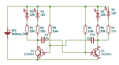
For an interactive BOM, see ibom.